前のページに戻ります
![이미지]() 2D 도면 다운로드
3D 도면 다운로드
Catalog 다운로드
2D 도면 다운로드
3D 도면 다운로드
Catalog 다운로드
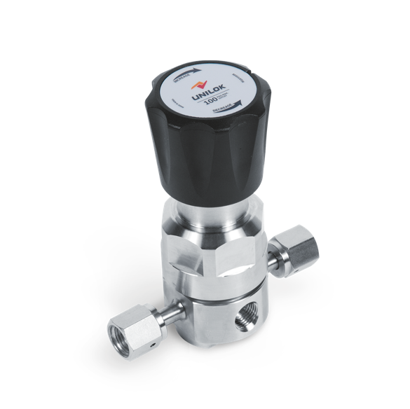
RC01 series
Non-Tied Diaphragm, Midium Flow
カテゴリー
- UHP | Regulator | RC01 series
PDF 다운로드
- Dimensions
- How To Order
- Specification
- Features
Dimensions
| Part No. | End Connection | Dimensions(mm) | |||
| Inlet | Outlet | L ± 1 | |||
| RC01 | U-04T- | 1/4” UNILOK Tube Fitting | 109.7 | ||
| C-04M- | 1/4” Male UCR Swivel | 94 | |||
| C-04F- | 1/4” Female UCR Swivel | 94 | |||
| C-04MF- | 1/4” Male UCR Swivel | 1/4” Female UCR Swivel | 94 | ||
| C-04FM- | 1/4” Female UCR Swivel | 1/4” Male UCR Swivel | 94 | ||
| C-08M- | 1/2” Male UCR Swivel | 120.7 | |||
| C-08F- | 1/2” Female UCR Swivel | 120.7 | |||
| WB-04T- | 1/4” Tube Butt Weld | 76.2 | |||
How To Order
| RC01 | C | - | 04F | - | 22 | 2 | 2 | - | 4 | ||||
| Regulator Type | Connection Type | Connection Size | Inlet / Outlet Pressure | Gauge Port Option | Outlet Gauge | Inlet Gauge | Body Material | Surface Finish | Trim Material | Seat Material |
| Regulator Type | Gauge Port Option | Inlet Gauge | |||||||||||
| RC01 | RC01 Series | 0 | None (Fig. A) | None | No Gauge | ||||||||
| 1 | 1/4“ Internal UCR (Fig. B) | A | 0~600 psig | ||||||||||
| Connection Type | 2 | 1/4“ Internal UCR (Fig. C) | B | 0~1000 psig | |||||||||
| C-*M | Male UCR Swivel | 3 | 1/4“ Internal UCR (Fig. D) | C | 0~2500 psig | ||||||||
| C-*F | Female UCR Swivel | 4 | 1/4“ Male Swivel (Fig. B) | D | 0~3500 psig | ||||||||
| WB-*T | Tube Butt Weld | 5 | 1/4“ Male Swivel (Fig. C) | E | 0~4000 psig | ||||||||
| U-*T | UNILOK Tube Fitting | 6 | 1/4“ Male Swivel (Fig. D) | ||||||||||
| 7 | 1/4“ Female Swivel (Fig. B) | Body Material | |||||||||||
| Connection Size | 8 | 1/4“ Female Swivel (Fig. C) | 2 | 316L VAR Stainless Steel | |||||||||
| 04 | 1/4 inch | 9 | 1/4“ Female Swivel (Fig. D) | 4 | 316L Stainless Steel | ||||||||
| 08 | 1/2 inch | ||||||||||||
| Outlet Gauge | Internal Surface Finish | ||||||||||||
| None | No Gauge | None | EP – Electro Polished | ||||||||||
| Maximum Inlet Pressure | 0 | 0~30 psig | BA | BA | |||||||||
| 1 | 3500 psig (0.06 Cv) | 1 | 0~60 psig | ||||||||||
| 2 | 600 psig (0.15 Cv) | 2 | 0~100 psig | Trim Material | |||||||||
| 4 | 3500 psig (0.15 Cv) | 3 | 0~160 psig | None | 316 SS | ||||||||
| 5 | 1250 psig (0.15 Cv) | 4 | 0~200 psig | H | Hastelloy® | ||||||||
| 5 | 0~300 psig | ||||||||||||
| Outlet Pressure Range | Seat Material | ||||||||||||
| 0 | 1~30 psig / 0.1~2.1 bar | None | PCTFE | ||||||||||
| 1 | 1~60 psig / 0.1~4.1 bar | V | PI | ||||||||||
| 2 | 1~100 psig / 0.1~6.9 bar | D | PVDF | ||||||||||
| 3 | 1~150 psig / 0.1~10.3 bar | ||||||||||||
| 4 | 1~250 psig / 0.1~17.2 bar | ||||||||||||
Specification
| Pressure Ratings | |||||
| Per criteria of ANSI/ASME B31.3 | Media Contact Materials | ||||
| Max. Inlet Pressure | 600, 1250, 3500
psig (41.4, 86.2, 241 bar) | Body | 316L Stainless Steel | ||
| Diaphragm | Hastelloy® | ||||
| Outlet Pressure Range | 30,
60, 100, 150 and 250 psig (2.1, 4.1, 6.9, 10.3 and 17.3 bar) | Seat | PCTFE (Optional PI) | ||
| Spring | 316L Stainless Steel or Inconel® | ||||
| Design Proof Pressure | 150% of maximum rated | Poppet, Retainer | 316L Stainless Steel or Hastelloy® | ||
| Operating Temperature | Internal Surface Finish | ||||
| PCTFE Seat | -40~60℃ (-40℉~140℉) | Designator | Surface Finish(µm) | ||
| PI Seat | -40~177℃ (-40℉~350℉) | Average | Maximum | ||
| PVDF Seat | -40~71℃ (-40℉~160℉) | BA | < 0.4 | < 1.6 | |
| EP | < 0.125 | < 0.4 | |||
| Flow Capacity | |||||
| 3500 psig / 241 bar | 0.06 Cv (Optional 0.15 Cv) | ||||
| 600 psig / 41.4 bar | 0.15 Cv | ||||
| Helium Leak Test | |||||
| Inboard Leak Rate | 1x10⁻⁹ atm cc/sec | ||||
Features
· The RC01 series provides excellent stability of set pressure with accuracy and sensitivity.
· Metal to metal diaphragm seals provide enhanced leak integrity
· Optimum performance and cleanliness at a great value
· Low internal volume
· Adjustable stop to limit outlet pressure
· All performed in Class 100 and Class 10 clean rooms.
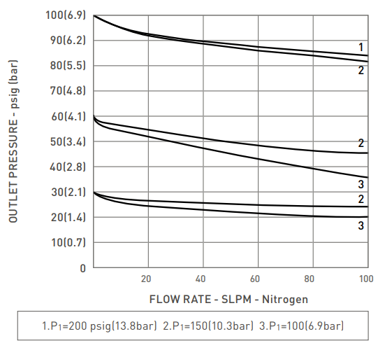
Flow chart


 top
top

