Category
- Instruments | Tube Fittings | Tube to Welded System
- Dimensions
- How To Order
- Tubing & Pipe end Thread Information
- Features
Dimensions
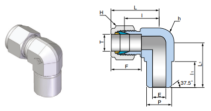
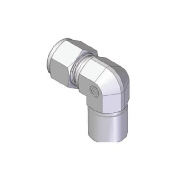
| Connects Fractional Tube to Pipe Butt Welded System | ||||||||||||||
| Part No. | Tube OD T | P (BW) | Dimensions (mm) | |||||||||||
| E Min. | h | H | F | I | I1 | L | L1 | |||||||
| inch | mm | Nom | O.D. | inch | mm | inch | mm | |||||||
| UWBE-0202P | 1/8 | 3.17 | 1/8 | 10.30 | 2.3 | 1/2 | 12.70 | 7/16 | 11.11 | 12.7 | 18.3 | 9.7 | 24.9 | 18.8 |
| UWBE-0404P | 1/4 | 6.35 | 1/4 | 13.70 | 4.8 | 1/2 | 12.70 | 9/16 | 14.28 | 15.2 | 19.6 | 13.8 | 26.9 | 23.4 |
| UWBE-0604P | 3/8 | 9.52 | 1/4 | 13.70 | 7.1 | 5/8 | 15.87 | 11/16 | 17.46 | 16.8 | 23.1 | 14.0 | 30.5 | 25.4 |
| UWBE-0808P | 1/2 | 12.70 | 1/2 | 21.30 | 10.4 | 13/16 | 20.63 | 7/8 | 22.22 | 22.9 | 25.9 | 19.0 | 36.1 | 33.0 |
| UWBE-1212P | 3/4 | 19.05 | 3/4 | 26.67 | 15.7 | 1-1/16 | 26.98 | 1-1/8 | 28.57 | 24.4 | 29.7 | 19.0 | 39.9 | 36.8 |
How To Order
Fractional(Inch)Tube fittings
UNILOK fractional(inch) size tube fittings are ordered by part number as shown below.
Example: The following part number, UMC-0804N-SS, is designated for Male Connector, 1/2"OD x 1/4" Male NPT, 316SS.
U | WBE | - | 08 | 04 | N | - | SS | ||
UNILOK | Fitting Type | Tube O.D. | Pipe Size | Thread Type | Material | NACE | Plating | ||
| Fractional(inch) Tube Designation | |||||||||||||||||
| Tube O.D. | inch | 1/16 | 1/8 | 3/16 | 1/4 | 5/16 | 3/8 | 1/2 | 5/8 | 3/4 | 7/8 | 1 | 1-1/8 | 1-1/4 | 1-1/2 | 2 | |
| mm | 1.50 | 3.17 | 4.76 | 6.35 | 7.93 | 9.52 | 12.70 | 15.88 | 19.05 | 22.22 | 25.40 | 28.57 | 31.75 | 38.10 | 50.80 | ||
| Designator | 01 | 02 | 03 | 04 | 05 | 06 | 08 | 10 | 12 | 14 | 16 | 18 | 20 | 24 | 32 | ||
| Pipe Size Designation | Material Designation | ||||||||||||||||
| Pipe Size | 1/8 | 1/4 | 3/8 | 1/2 | 3/4 | 1 | 1-1/4 | 1-1/2 | 2 | Designator | Materials | ||||||
| Designator | 02 | 04 | 06 | 08 | 12 | 16 | 20 | 24 | 32 | SS | 316SS | ||||||
| BS | Brass | ||||||||||||||||
| Thread Type Designation | CS | Carbon Steel | |||||||||||||||
| Designator | Thread Type | MO | Alloy 400 | ||||||||||||||
| N | NPT | National Standard Pipe Thread | IN60 | Alloy 600 | |||||||||||||
| R | ISO 7/1 | Taper Pipe Thread | IN65 | Alloy 625 | |||||||||||||
| G | ISO 228/1 | Parallel Pipe Thread | IN85 | Alloy 825 | |||||||||||||
| U | SAE J1926 | Straight Thread Boss | HC | Alloy C-276 | |||||||||||||
| S | SAE J514 | 37° Flared | TF | PTFE | |||||||||||||
| T | Tube End | DP | Duplex | ||||||||||||||
| None | UNILOK Port | SD | Super Duplex | ||||||||||||||
| 6MO | 6MO/SMO254 | ||||||||||||||||
| NACE Application | Plating Designation | ||||||||||||||||
| None | - | NP | Nickel | ||||||||||||||
| N | NACE Application | BP | Black Phosporized | ||||||||||||||
Metric Tube Fittings
UNILOK metric size tube fittings are ordered by part number as shown below.
Example: The following part number, UMC-M1204R-SS is designated for Male Connector, 12mmOD x 1/4" Male BSPT, 316SS.
| U | WBE | - | M12 | 04 | R | - | SS | ||
| UNILOK Tube Fittings | Fitting Type | Tube O.D. | Pipe Size | Thread Type | Material | NACE | Plating | ||
| Metric Tube O.D Designation | |||||||||||||||||||
| Tube O.D. | mm | 2 | 3 | 4 | 6 | 8 | 10 | 12 | 14 | 15 | 16 | 18 | 20 | 22 | 25 | 28 | 32 | 38 | |
| Designator | M02 | M03 | M04 | M06 | M08 | M10 | M12 | M14 | M15 | M16 | M18 | M20 | M22 | M25 | M28 | M32 | M38 | ||
Tubing & Pipe end Thread Information
Tubing Information
The proper selection of tubing is essential to assure maximum fitting reliability and performance. When choosing tubing material, size and wall thickness, consider system’s pressure, flow rate, temperature, environment and compatibility with great care.
Maximum Allowable Working Pressure
Stainless Steel Tubing
Fully annealed and seamless stainless steel tubing to comply with ASTM A269 or equivalent. Hardness should not exceed Rb 80. Tubing should be free from scratched and suitable for bending and flaring.
| Fractional(Inch) Tubing | |||||||||||
| Tube O.D. (inch) | Tube Wall Thickness (inch) | ||||||||||
| 0.028 | 0.035 | 0.049 | 0.065 | 0.083 | 0.095 | 0.109 | 0.120 | 0.134 | 0.156 | 0.188 | |
| 1/8 | 8550 | 10950 | |||||||||
| 3/16 | 5500 | 7100 | 10300 | ||||||||
| 1/4 | 4100 | 5200 | 7600 | 10300 | Working pressure in psig | ||||||
| 5/16 | 4100 | 5900 | 8100 | ||||||||
| 3/8 | 3350 | 4850 | 6550 | ||||||||
| 1/2 | 2650 | 3750 | 5150 | 6750 | |||||||
| 5/8 | 2950 | 4050 | 5250 | 6050 | |||||||
| 3/4 | 2450 | 3350 | 4250 | 4950 | 5850 | ||||||
| 4/8 | 2050 | 2850 | 3650 | 4250 | 4850 | ||||||
| 1 | 2400 | 3100 | 3600 | 4200 | 4700 | ||||||
| 1-1/4 | 2400 | 2800 | 3300 | 3600 | 4100 | 4900 | |||||
| 1-1/2 | 2300 | 2700 | 3000 | 3400 | 4000 | 4900 | |||||
| 2 | 2000 | 2200 | 2500 | 2900 | 3600 | ||||||
| Metric Tubing | |||||||||||
| Tube O.D. (inch) | Tube Wall Thickness (inch) | ||||||||||
| 0.8 | 1.0 | 1.2 | 1.5 | 2.0 | 2.2 | 2.5 | 3.0 | 3.5 | 4.0 | 4.5 | |
| 3 | 9700 | ||||||||||
| 4 | 7900 | 11500 | |||||||||
| 6 | 4500 | 6100 | 7850 | 10300 | Working pressure in psig | ||||||
| 8 | 4500 | 5650 | 7500 | ||||||||
| 10 | 3500 | 4350 | 5800 | 8400 | |||||||
| 12 | 2900 | 3600 | 4800 | 6800 | |||||||
| 14 | 2300 | 2900 | 4000 | 5500 | 6250 | ||||||
| 15 | 200 | 2750 | 3650 | 5200 | 5800 | ||||||
| 16 | 2450 | 3350 | 4800 | 5350 | 5800 | ||||||
| 18 | 2150 | 2950 | 4200 | 4650 | 5350 | ||||||
| 20 | 2030 | 2600 | 3750 | 4200 | 4800 | ||||||
| 22 | 1750 | 2300 | 3350 | 3750 | 4350 | ||||||
| 25 | 2900 | 3350 | 3750 | 4650 | |||||||
| 38 | 2030 | 2300 | 2900 | 3500 | 3900 | 4500 | |||||
| For gas service application, use only tubing with wall thickness on outside of gray areas. Allowable stress of 20000 psig between -29°C(-20°F) and 37°C(100°F) based on ultimate tensile strength to be 74000 psig. | |||||||||||
Copper Tubing
Fully annealed and seamless stainless steel tubing to comply with ASTM B75 or equivalent. Hardness should not exceed Rb 60.
Fractional(Inch) Tubing
| Tube O.D. (inch) | Tube Wall Thickness (inch) | |||||||
| 0.028 | 0.035 | 0.049 | 0.065 | 0.083 | 0.095 | 0.109 | 0.120 | |
| 1/4 | 1300 | 1600 | 2500 | 3500 | ||||
| 3/8 | 1000 | 1600 | 2200 | |||||
| 1/2 | 800 | 1100 | 1600 | 2200 | ||||
| 5/8 | 900 | 1200 | 1600 | 1900 | ||||
| 3/4 | 700 | 1000 | 1300 | 1500 | 1800 | |||
| 1 | 500 | 700 | 900 | 1100 | 1300 | 1500 | ||
Metric Tubing
| Tube O.D. (inch) | Tube Wall Thickness (inch) | ||||
| 1.0 | 1.5 | 2.0 | 2.5 | 3.0 | |
| 6 | 2350 | 3670 | |||
| 8 | 1710 | 2680 | Working pressure in psig | ||
| 10 | 1350 | 2090 | |||
| 12 | 1100 | 1710 | 2350 | ||
| 20 | 990 | 1350 | 1710 | ||
| 25 | 780 | 1060 | 1350 | 1640 | |
For gas service application, use only tubing with wall thickness on outside of gray areas. Allowable stress of 6000 psig between -29℃(-20℉) and 37℃ (100℉) based on ultim ate tensile strength to be 30000 psig.
Monel Tubing
Fully annealed and seamless stainless steel tubing to comply with ASTM B165 or equivalent. Hardness should not exceed Rockwell Rb 75.
Fractional(Inch) Tubing
| Tube O.D. (inch) | Tube Wall Thickness (inch) | ||||||
| 0.035 | 0.049 | 0.065 | 0.083 | 0.095 | 0.109 | 0.120 | |
| 1/4 | 4800 | 7000 | 9500 | ||||
| 3/8 | 3100 | 4400 | 6100 | Working pressure in psig | |||
| 1/2 | 2300 | 3200 | 4400 | ||||
| 3/4 | 2200 | 3000 | 4000 | 4600 | |||
| 1 | 2200 | 2900 | 3400 | 3900 | 4300 | ||
For gas service application, use only tubing with wall thickness on outside of gray areas. Allowable stress of 6000 psig between -29℃(-20℉) and 37℃ (100℉) based on ultimate tensile strength to be 30000 psig.
Determination Factors of MAWP at High Temperature Application
To determine allowable working pressure at elevated temperature, multiply allowable working pressure and factors which are shown in the table.
| Temperature | Materials | |||
| ℃ | ℉ | 316SS | Copper | Monel |
| 90 | 194 | 1.0 | 0.8 | 0.88 |
| 200 | 392 | 0.96 | 0.5 | 0.79 |
| 310 | 590 | 0.85 | - | 0.79 |
| 480 | 802 | 0.79 | - | 0.75 |
| 536 | 996 | 0.76 | - | - |
| 644 | 1227 | 0.37 | - | - |
Example: 316SS Tubing, 1/2"ODx0.049"WT at 310℃ AWP: 3750 x 0.85 = 3187 psig.
* MAWP: Maximum Allowable Working Pressure
* AWP: Allowable Working Pressure
Pipe End Thread Information
The end connections with the lower pressure rating is the determining factor of pressure rating for the fittings with both UNILOK tube ends and pipe thread ends .
Pressure Rating for Pipe End Thread
| Tapered Pipe Threads - NPT or ISO 7/1(BSPT) Allowable pressure ratings for male and female threads are based on ASME B31.3 at ambient temperature. | ISO 228/1 Parallel Thread (BSPP) The pressure ratings are at ambient temperature. | ||||||||||||
| Pipe Size | 316SS | 316SS | UNILOK Desig nator | Male Pipe Size | 316SS | UNILOK Designator | |||||||
| Male | Female | Male | Female | bar | psig | ||||||||
| inch | bar | psig | bar | psig | psig | bar | psig | 1/8 | 315 | 4568 | -02G | ||
| 1/16 | 760 | 11000 | 460 | 6700 | 5500 | 230 | 3300 | -01N/R | 1/4 | 315 | 4568 | -04G | |
| 1/8 | 690 | 10000 | 440 | 6500 | 5000 | 220 | 3200 | -02N/R | 3/8 | 315 | 4568 | -06G | |
| 1/4 | 550 | 8000 | 450 | 6600 | 4000 | 220 | 3300 | -04N/R | 1/2 | 160 | 2320 | -08G | |
| 3/8 | 540 | 7800 | 360 | 5300 | 3900 | 180 | 2600 | -06N/R | |||||
| 1/2 | 530 | 7700 | 330 | 4900 | 3800 | 160 | 2400 | -08N/R | |||||
| 3/4 | 500 | 7300 | 320 | 4600 | 3600 | 160 | 2300 | -12N/R | |||||
| 1 | 370 | 5300 | 300 | 4400 | 2600 | 150 | 2200 | -16N/R | |||||
| 1-1/4 | 410 | 6000 | 350 | 5000 | 3000 | 170 | 2500 | -20N/R | |||||
| 1-1/2 | 340 | 5000 | 310 | 4600 | 2500 | 150 | 2300 | -24N/R | |||||
| 2 | 270 | 3900 | 270 | 3900 | 1900 | 130 | 1900 | -32N/R | |||||
O-Seal Fittings
Rated to 206 bar (3000 psig) for 316SS fittings up to 1 inch and 25mm
Kinds of Pipe End Thread
NPT Pipe Thread | ISO 7/1 Tapered Pipe Thread | ISO 228/1 Parallel Pipe Thread | ||||||||||
Features
Gaugeability
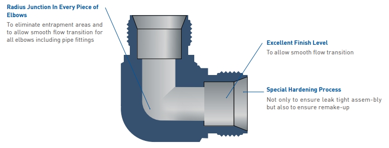
UNILOK tube fittings are produced with exact and tight tolerances. Without such close tolerances, proper interaction among the nut, ferrules, and body would not occur.
Corrosion Resistance
UNILOK ferrules have the strongest corrosion resistance due to our own special hardening process.
This has been proven in various industrial areas over several decades.
Interchangeability
UNILOK tube fittings can be interchanged with tube fittings manufactured to international standards.
Less Torque and Anti-Distortion
When the nut is tightened, both ferrules are driven forward between the nut and the body.
This axial movement doesn't transfer any torque from the fitting to the tubing when the original tubing's mechanical properties are maintained.
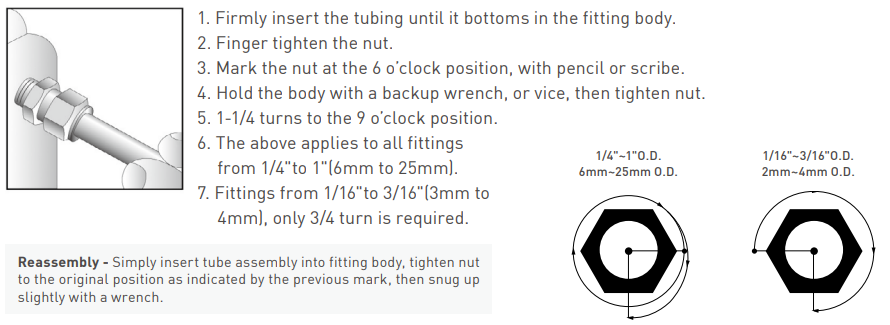
UNILOK Tube Fittings Installation Instruction







 top
top

